Ideafiles
Opinions
Photography
My BMW
Toscana
About
the
Ideaphile
About This Site
I spent a lot of time picking a way to drive the saw blades.
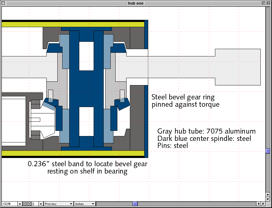
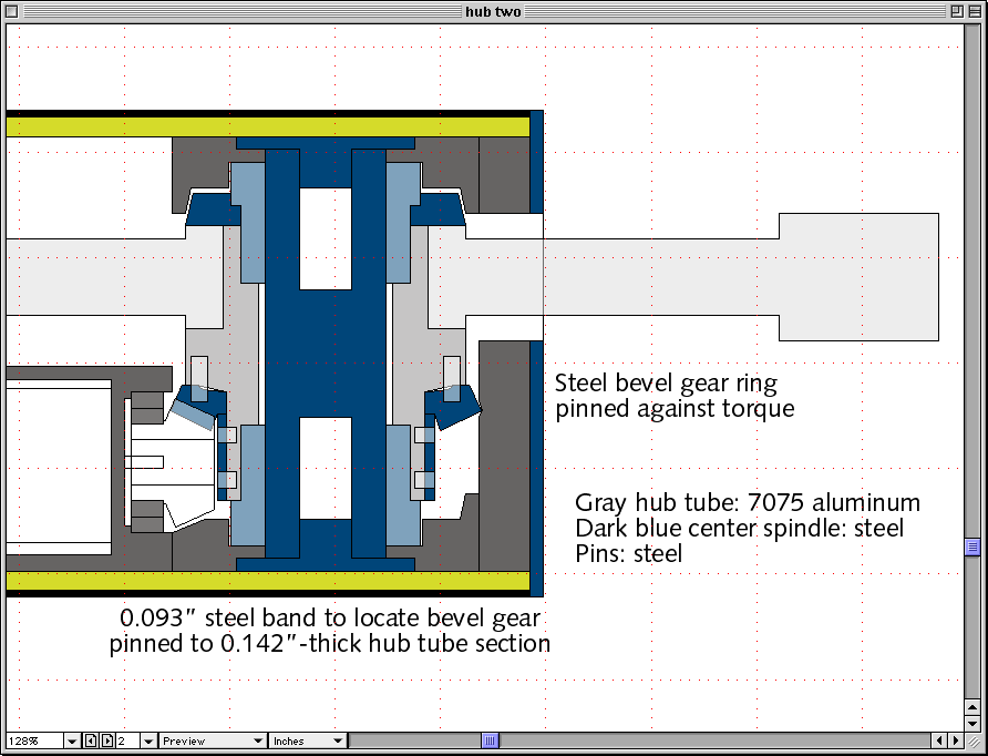
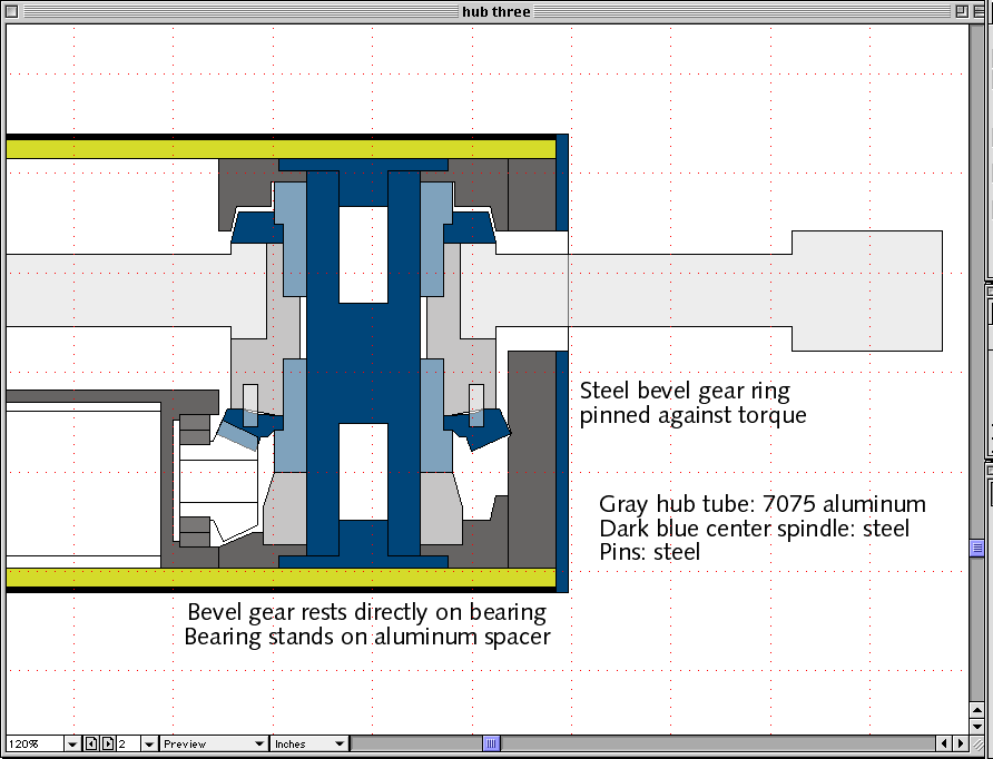
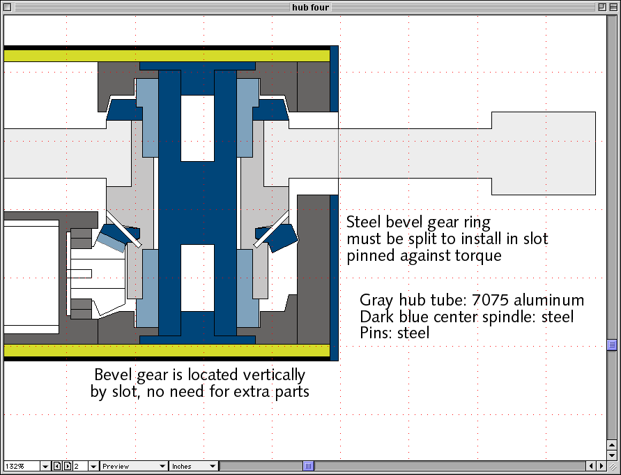
These Aveox electric motors are plenty strong enough to spin up my saw blades when used with a set of bevel gears that provide a 3:1 speed reduction. Each blade will be mounted to a hub tube, along with the outer ring of the bevel gear. The blade mount is easy, because it's got such a huge bearing surface and hefty built-in keyway slots. It took me a while to decide how to attach the bevel gear. I considered four alternatives, drew the diagrams shown below, then picked one and had some parts built for testing.
A heavy steel shoulder
In this concept, the bevel gear is pinned up into the hub tube, and located vertically by a thick steel tube section that rests on the shoulder in the bearing. The bevel gear and the hub tube rest on the shoulder of the steel tube. In addition to the pins, I'd use a metal-bearing epoxy to fill out the voids in the irregular sections of the bevel gear.
A thinner steel sleeve
The bevel gear is pinned up into the hub tube, and located vertically by a steel sleeve that is pinned (or screwed) into the hub tube, which extends down to the bearing shoulder.
Short tube
The bevel gear is pinned up into the hub tube, and rests directly on the bearing shoulder. The bearing is raised up to the necessary height by an aluminum support ring that fits snugly around the center spindle rod. The motor is lowered to provide enough room for everything here.
The split gear approach
The bevel gear could be split in half and set into a slot milled around the circumference of the hub tube. This alternative has the fewest parts and the greatest mechanical strength in the hub tube, but compromises the strength of the bevel gear itself. Each half of the bevel gear must be pinned into the hub tube somehow to resist torque and radial forces that would tend to pull it out. Because the bevel gear is set into a slot, it won't be easy to install pins.
This was the scheme I chose as the basis for my first prototype. The pin locations shown here have already been changed, as has the clamp plate between the saw hub and the top bearing, but this picture shows the basic concepts.
The parts
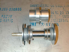
The tableau depicted below includes all of the parts I had manufactured for the prototype hub assembly. At the top left is shown one washer, the 30mm shaft that acts as the inner bearing race, and an AN-8 aircraft bolt.The matching washer for the other side of the 'bot is at the lower left, followed by the combination needle shell / cylinder roller thrust bearing assembly, the custom-made hub fabricated out of 7075-T651 aluminum alloy by Tool Engineering in Campbell, CA, and another bearing with the clamp washer that holds the saw blade on the hub. The three washers are all made of S-7 tool steel. The choice of that material was mostly a matter of convenience. They haven't been hardened yet; I want to know if there's enough force on the assembly to bend any of these components in their annealed state. Once I'm satisfied with the design and manufacture the final parts, I'll have them hardened properly.
The parts stacked up
This pictures show all of these parts assembled in their proper order, except for the hub, saw blade, and bevel gear. The bearings were a nice snug press fit into the hub-- I guess I got the dimensions right. Yay. :-)
The clamp washer
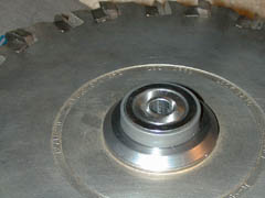
The saw-blade clamp washer fits between the saw blade and the bearing. The outer diameter of the clamp washer matches the diameter of the saw blade's integrated flange. This picture shows the 30mm shaft inserted into the bearings. There's no play left in the fit between the shaft and the bearings, but it's still free to turn easily, which suggests the bearings fit properly.
The assembly in the test stand
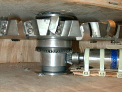
This is what the whole assembly looks like in my plywood test stand. The bevel gear has been installed in its slot in the hub, and the Aveox motor has been positioned and shimmed to give the right engagement between the gears.
The first time I powered it up, it ran up to a couple of thousand RPM quite smoothly and easily.
The second time, I blew up a capacitor in the speed controller.:-)
After replacing the capacitor I made a few dozen tests up to about 2,500 RPM, and it seems pretty solid. The controller and its caps still run really hot, so I'm upgrading the controller. Once that's done, I'll be able to see just how fast this thing will spin, and what happens when I toss big heavy pieces of metal at it. I've also lubricated the gears with a heavy moly-bearing grease, and I've installed a tachometer pickup so I can know exactly how fast it's going. Stay tuned for more results as they come in.
Home
Site Map
Back to top
Ideafiles | Opinion | Photography | My BMW | Toscana | About the Author
If you have comments or suggestions, please email me at png@ideaphile.com.
All content copyright 1996-2000 by Peter N. Glaskowsky. All rights reserved.
